All about Microcontroller (Part-6)
My writing today is also about programmers. Today I will show you how to make a cracked USB Programmer for PIC Micro controller.
I told you earlier in a tune that Microchip, the maker of PIC Micro controller, has put up a USB Programmer's design, necessary software, firmware on their website for free to increase the promotion and use of their controller. You just have to make it. You can also buy readymade if you want. The programmer is named PICkit. The current version of PICkit3 is running, but PICkit2 is the most popular version. Our programmer will be PICkit2
Let's find out what are the features of PICkit2.
Since the cost to buy or build PICkit2 is very low, we can say that it is a low cost programmer.
With PICkit2 you can create baseline (PIC10F, PIC12F5xx, PIC16F5xx), midrange (PIC12F6xx, PIC16F), PIC18F, PIC24, dsPIC30, dsPIC33, PIC32 families of 8-bit, 16-bit, and 32-bit micro controllers and MicroPRO Can.
PICkit2 is not just for programmers, it also allows you to do debugging. While in the micro controller circuit, you can integrate with programming and MPLAB software, complete the instruction one by one, or stop the program at any time to view or change the value of different file registers. In other words, we can call PICkit2 In Circuit Serial Programmer and In Circuit Debugger.
You can also use PICkit2 as a 500kHz Logic Analyzer and serial communication (UART) tool.
Another interesting feature is that you can save your program in EEPROM located in the programmer and program Micro controller without computer using Programmer to Go function. In that case only PICkit2 has to arrange the required power.
Let's take a look at the circuit diagram.
Attempts have been made to draw the circuit as cleanly as possible. Notice that I have added some connections through the terminal. Suppose VDD_ADJ terminal is connected to one end of R18 in the input of IC2A. The VDD_ADJ terminal is connected to pin 13 of IC1. This means that one end of the R18 must be connected to pin 13 of IC1. If I were to draw a whole diagram with a terminal, the whole diagram would be like a spider's web.
To understand how the circuit works, we will divide it into different parts.
Download the required PCB layout, circuit diagram, parts list from the link below.
Download PICkit2's software from the link below.
Or
Along with my writing, you can print the circuit diagram to better understand the operation of the circuit and to shoot the trouble later. It will be useful to understand.
First of all, let's get the power supply, the whole circuit is getting power from the computer's USB. Notice in the diagram above, the VCC pin of the USB connector is connected to the + 5V terminal and its GND pin is connected to the ground of the circuit. This + 5V terminal will supply power to the entire circuit.
We know that some of the PIC micro controllers work at 3.3V and some at 5V. So according to the model of micro controller, the programmer has to apply different voltage to the VDD pin of ICSP as a supply. For this the programmer has a voltage regulator. You can regulate voltage from 2.5V to 5V. Just separate the voltage regulator for ease of understanding. See the picture below.
One end of the R18 Resistor is connected to the ccp1 pin of the pic18f2550 micro controller via the VDD_ADJ terminal. The CCP1 and CCP2 of the microcontroller are both PWM pins. And with PWM you can change the average voltage by changing the width of the pulse by keeping the frequency right. Thus the pic18f2550 microcontroller uses PWM at the inverting input (pin 2) of the IC2A Operational amplifier (OPAMP for short) as an average DC voltage reference. In this case R18 and C6 are used to filter the PWM and remove the ripple. OPAMP will always try to equalize the voltage of inverting input (pin 2) and non-inverting input (pin 3) by changing its output voltage. What rate will change depends on his feedback. As a result of giving reference voltage to pin 2, OPAMP will reduce the voltage at its output and turn on PNP Transistor Q2 in linear mode. When Q2 is on, the voltage will be divided by R21 and R22 as feedback to the non-inverting input. Thus OPAMP will regulate the output voltage.
The Q3 transistor is connected to pin 25 of the microcontroller via the VDD_TGT_P terminal. This allows the microcontroller to turn the voltage on or off the two pin pins of the ICSP to the VDD. Notice the complete circuit diagram. The collector of the Q3 transistor is connected to pin number two of the ICSP via the V_TGT terminal. Now the question is how the microcontroller will understand how much voltage is in the VDD pin of ICSP and whether the width of the pulse of PWM in VDD_ADJ terminal should be reduced or increased. You don't need feedback for this !!
The pin number 2 of the ICSP becomes the R34 resistor and is connected to the Analog Inut pin of the microcontroller's pin number 3 via the VDD_TGT_FB terminal. Also, if for some reason the VSPD pin of ICSP is short-circuited with the ground, the microcontroller will turn off the Q3 Transistor and save the programmer from crashing.
Now let's discuss VPP. We know that in some cases a voltage of around 12 volts must be applied to the microcontroller's VPP pin to enter programming mode. But the supply voltage of our USB programmer is 5 volts then how will 12 volts come. Notice in the circuit that the output of the Voltage Regulator uses a very simple Boost Converter. We can also call it DC to DC converter. Only this part is shown separately below.

The whole circuit above but not the DC to DC converter. From the left side to the C11 capacitor is our desired part. The rest is just switching.
One end of the L1 is connected to the output of the voltage regulator, I have used the V_TGT terminal to understand. The V_TGT terminal is the output of the Voltage regulator. The base R17 resistor of the T1 transistor is connected to the CCP2 pin of the microcontroller via the VPP_PUMP terminal. The second PWM output pin of the CCP2 microcontroller.
Now let's think about what happens when the T1 transistor is turned on and off. When the T1 transistor is on, the current coming from the voltage regulator will flow towards the ground through T1 through L1 Inductor. Simply put, current will flow through the L1 Inductor. We know that if current flows through an inductor, it will create magnetic flux. This magnetic flux stores energy inside the inductor. Now if you turn off the T1 transistor, the previous current will not flow through T1. But we know that Inductor always prevents change of current. The inductor will try to hold its previous current. The impedance of the front of the inductor was almost zero when the T1 transistor was on. Because the T1 transistor short-circuited one end of the inductor with the ground. But as soon as the T1 transistor is turned off, the rest of the circuit is connected to the inductor and increases the impedance of the circuit. This time the inductor will try to make the previous current flow through the additional impedance. According to Ohm's law the excess impedance will try to reduce the current or increase the voltage. Since the inductor does not agree to reduce the current, the voltage will increase. This voltage will be forward biased and charge the capacitor as there is a p-n junction between the base and collector of T2. The capacitor cannot be discharged when T1 is on because the base of T2 and the p-n junction in the collector are reversed biased and do not allow the capacitor to discharge. Now if you turn T1 on and off very quickly you will get more Steady output voltage than the input at both ends of the capacitor. The amount of output voltage you get depends on the T1's on-off time. The microcontroller does this via PWM. This time he has to take feedback to fix the duty time of PWM. Feedback is given by making a voltage divider with R10 and R11 in the circuit and connecting the 2nd pin of the microcontroller with the analog input pin through the VPP_FB terminal. The voltage divider is given here because the voltage here is about 12 volts and the microcontroller cannot measure more than 5 volts. So the voltage has been reduced with a voltage divider.
Why the voltage in the inductor is high due to switching could be explained with the change of flux but I am not going that way anymore.
Diode can be used in place of T2. However, Schottky diode must be used. 1N5817, Bat45 These are the model numbers of Schottky diode. The T2 transistor has been used because the Schottky diode is not available everywhere. Diode E is commonly used in place of T2 everywhere.
Click here to know about Boost Converter.
The microcontroller is turning on the T5 transistor through the VPP_ON terminal, so the Q4 transistor is also turned on. And turning on Q4 means VPP voltage reaches pin number 1 of ICSP.
The microcontroller turns on the T4 Transistor via the MCLR_TGT terminal to ground the MCLR or VPP pin.
The ICSP FOR SELF connector is used to program the pic18f2550 micro controller located in the programmer with another programmer's ICSP connector. Also, if you don't want to use the programmer to Go programming program without a computer, there is no problem if you don't use IC3 and IC4 EEPROM. I did not use ICSP FOR SELF and EEPROM.
I am not writing about how to make the programmer in PCB. In my previous tune, I wrote about PCB.
Click here to see the previous part.
Then let's take a look at some pictures of PCB layout and making time from below.

As you can see in the picture above, the PCB layout of PICkit2.

The figure above shows where and how to install any parts in the PCB. Wire links (short link or jumper) are shown in red.


pic18f2550 The microcontroller needs to be programmed before it can be mounted on the board. The program file is given in the Firmware folder. You will need the help of another programmer to program the microcontroller.Will be able to program itself through.
Now it's your turn to test your programmer. Before connecting your programmer to the computer's USB, check to see if the pins on the programmer's USB connector are sorted with each other during soldering. You do not want any damage to your computer. Connect the programmer to the computer with a USB cable. Now install PICkit2 software and run it. It would be better to run Administrator in Windows 7.
If all goes well, the following window will open

Now clicking on Tools> troubleshoot ... will open the following window.

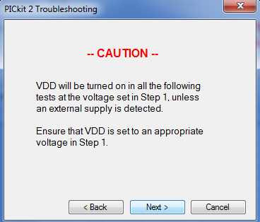
Press Next

Now leave as much voltage as you want in the VSPD pin of ICSP and click on Test button. With a good multimeter you can measure the voltage between VDD and GND to see if it is OK. If OK then it will look like the following window.

VDD Test Complete Now it's time to test VPP. Press Next. PICkit2 will give you a warning to adjust the VDD. That means you have to be sure to test the VPP with how many VDDs you have. You can test VPP on different VDDs. 12 volts should come to VPP every time. All the 16f family VPP of about 12 volts.
Press next.
Those who have an Oscilloscope can check that the data and clock signals on the PGD and PGC pins are correct. Press the Toggle 30kHz button twice.

Now it's time to program. Connect your microcontroller to the programmer with the ICSP connector. Check out which ICSP PIN is below.

Now see below which pins of ICSP you will add to which pins of the microcontroller you will program.

Understand that the VSP / MCLR, VDD, GND, PGD, PGC pins of ICSP need to be connected to the VPP / MCLR, VDD, GND, PGD, PGC pins of the desired microcontroller respectively.
Those who want to use ZIF Socket will make the connection as per the diagram below.

See below for pictures of the PCB layout in this circuit diagram.

Download the pdf file of PCSP layout of ICSP and ZIF Socket from below.
My tutorial number 5 explains in detail how and where to install the pin controller in ZIF Socket. The connection of this ZIF Socket is similar to the connection of ZIF Socket used in that tutorial.

When PICkit2 is turned on while the microcontroller is connected, PICkit2 will automatically detect the microcontroller. When detected, select Import File from File. Show your programmed HEX file.
Now click on Write Device from Programmer. If all goes well, the microcontroller will be programmed.


If you want to change the configuration bit, you can do so by clicking on Configuration. If your Configuration word is 2ff2 then you can change 2ff2 to Binary i.e. 10111111110010, because in PICkit2 the Configuration word change window is given in Binary.

Stayed until today. I hope you make the programmer successful.
)
0 Comments