All about Microcontroller (Part-7)
Today we will see how to operate Alphanumeric LCD. There are different types of Alphanumeric LCDs available in the market, the most widely used being the 16x2 LCD display. This means 16x2, this LCD has a total of two lines and each line can display 16 characters. This means that only different types of characters can be displayed with this LCD. It is not possible to draw any kind of picture here. Character numbers can be of different types such as, 8, 16, 20, 24, 32, 40 and line numbers, 1, 2, 4. I will tell you later what characters can be displayed. Let's take a look at the LCDs from below.

The compatible chip of Hitachi HD44780 has been used in the LCD that I will discuss today. This LCD is no different from the Hitachi HD44780.
Click here to see the previous part.
The pin number of our LCD is 16. Of which 8 data lines, three control lines, three power lines, and two pins to power the LED. Let's see which pin.

Below is a table of what pins are doing.
PIN number | PIN name | PIN work |
1 | VSS | Ground pin |
2 | VDD | Positive voltage supply |
3 | VEE | Contrast adjustment pin of LCD |
4 | RS | Register Select PIN |
5 | R/W | Read / Write Select PIN |
6 | E | Enable PIN |
7 | D0 | Data Bit 0 |
8 | D1 | Data Bit 1 |
9 | D2 | Data Bit 2 |
10 | D3 | Data Bit 3 |
11 | D4 | Data Bit 4 |
12 | D5 | Data Bit 5 |
13 | D6 | Data Bit 6 |
14 | D7 | Data Bit 7 |
15 | LED+ | Positive supply of LED |
16 | LED- | Negative supply of LED |
PIN 1 is the ground pin of the LCD. This pin needs to be connected to Zero Volt or Pround.
Pin No. 2 Positive supply pin of LCD. LCD usually runs at 5 Volt. However, the LCD can run at 6 Volt or 4.5 Volt. In some cases 3 4.5 Volt is enough. The current consumption of LCD is very low, only a few milli amperes.
Pin 3 is the contrast pin of the LCD. The contrast of the LCD can be changed with this pin. Different voltages have to be applied to this pin to change the contrast. Usually the supply voltage is connected to this pin by dividing the voltage by a variable resistor. This allows the contrast to be changed as desired by turning the variable resistor.
PIN 4 is called Register Select PIN. This is the first pin to have three control pins on an alphanumeric LCD. If this pin is applied low i.e. 0 volts, the LCD will be in command mode. This means that the setting of the LCD will change. And if this pin is applied high i.e. 5 Volt, then the LCD will be in different character display mode.
The 5th pin of LCD is R / W or Read / Write pin. This pin is the second control pin of the LCD. To write any command or character in LCD, this pin has to be applied low i.e. 0 volts. And to read something from the LCD, this pin has to apply high i.e. 5 volts.
PIN 6 is the Enable PIN. This pin is the second control pin of the LCD. If you send data to the LCD data line, the LCD will not accept it unless this PIN is being lowered from High. Similarly no data can be read from LCD unless this PIN is going from Low to High.
These 8 (D0-D7) pins from pin 7 to pin 14 are the data line of the LCD. With these pins 8 bit data can be sent to LCD or received from LCD. This LCD can also be run in 4 (Two nibble) Bit mode. In that case you have to use these four pins from D4 to D7.
Let's do some fun experiments with LCD. Those who have LCD can experiment directly or do simulations in Proteus. I have explained about Proteus in detail in my fourth tutorial.
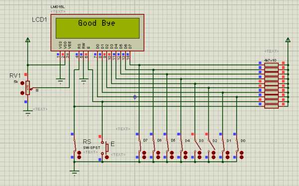
So let's make a connection like the following circuit.

Connect the two Vss and VDD pins directly to the ground and to 5 volts, respectively. Connect the VEE pin to a variable register as shown in the figure. The RW pin has been grounded because we will not read any data from the LCD but only write. So it is important to always keep the RW pin low. Also RW, E, D0 to D7 these ten pins are connected with 5V with a 4.7k ohm resistor and pull high and each pin is grounded by a switch. When the switch is on, the pin will be low i.e. logical 0 and if the switch is off, the pin will be high i.e. logical 1. Notice in the picture above that the switch used with Enable (6 number pin) is different from the others. The rest of the switches are latched type, which means they will be turned on when pressed and off when pressed again. And the Enable switch is momentary action type, that is, when pressed, it will be turned on and if left, it will be turned off again, much like a calling bell switch. The reason for using this type of switch in enable pins is that the LCD transfers data only during the high to low or low to high transition of this pin.
Place these eight switches from D0 to D7 in such a way that the Most significant bit (MSB) i.e. D7 is on the left and the least significant bit i.e. D0 is on the right.
Let's turn on the LCD.
If you start simulation by pressing Play Button on Proteus, the LCD will be turned on. If you actually work with LCD, you have to be careful about the contrast. In reality the LCD displays a number of black boxes on the first line as soon as it is turned on. The LCD has to be configured first before displaying anything.
You need to send some initializatio commands to the LCD to configure. To do this, the LCD needs to be taken in command mode. I have already said that the mode of LCD has to be changed via RS pin. Sending 0 to the RS pin changes to LCD command mode and sending 1 to LCD changes to Character mode. Then send the command to the LCD by turning on the RS switch and sending logical 0 to the RS pin. Now we will send ‘00001111’ data from pin D0 to D7. For this you need to turn the switches on or off according to the position of LSB and MSB. Below is a table showing which switches need to be switched on or off to send ‘00001111’ data.
D7 | D6 | D5 | D4 | D3 | D2 | D1 | D0 |
0 | 0 | 0 | 0 | 1 | 1 | 1 | 1 |
ON | ON | ON | ON | OFF | OFF | OFF | OFF |
Once the required switch is turned on / off, press and release the enable switch.
What can be seen on the LCD !!! If you do not make a mistake, the cursor will jump to the top left of the LCD. LCD has been initialized.

Now let's write some characters. To write the character, turn off the RS switch and send the logical 1 to the RS pin to take the LCD to character mode. Note, however, that the LCD will not display anything in command mode. RS pin must be 0 to give setting and RS pin must be 1 to write character. I won’t tell the RS pin what to do next, you have to figure it out on your own. Anyway now send ‘01000001’ to the data line and press and release the enable switch. BINGO !!!! The letter 'A' is written on the LCD. This time it is the turn of sweet food.

You must understand how to send data to LCD.
Below is a table of the data required to initialize. I will discuss this table later in breaking down as needed.
LCD Command Control Codes | ||||||||||||||||||||||||||||||||||||||||||||||
Command | Binary | Hex | ||||||||||||||||||||||||||||||||||||||||||||
D7 | D6 | D5 | D4 | D3 | D2 | D1 | D0 | |||||||||||||||||||||||||||||||||||||||
| Clear Display | 0 | 0 | 0 | 0 | 0 | 0 | 0 | 1 | 01 | |||||||||||||||||||||||||||||||||||||
| Display and Cursor Home | 0 | 0 | 0 | 0 | 0 | 0 | 1 | x | 02 or 03 | |||||||||||||||||||||||||||||||||||||
| Character Entry Mode | 0 | 0 | 0 | 0 | 0 | 1 | I/D | S | 01 to 07 | |||||||||||||||||||||||||||||||||||||
| Display On/Off and Cursor | 0 | 0 | 0 | 0 | 1 | D | U | B | 08 to 0F | |||||||||||||||||||||||||||||||||||||
| Display/Cursor Shift | 0 | 0 | 0 | 1 | D/C | R/L | x | x | 10 to 1F | |||||||||||||||||||||||||||||||||||||
| Function Set | 0 | 0 | 1 | 8/4 | 2/1 | 10/8 | x | x | 20 to 3F | |||||||||||||||||||||||||||||||||||||
| Set CGRAM Address | 0 | 1 | A | A | A | A | A | A | 40 to 7F | |||||||||||||||||||||||||||||||||||||
| Set Display Address | 1 | A | A | A | A | A | A | A | 80 to FF | |||||||||||||||||||||||||||||||||||||
|
| |||||||||||||||||||||||||||||||||||||||||||||
I used the Display On / Off and Cursor command in the table above to initialize. What is meant by D, U, B in the Display On / Off and Cursor lines is given at the bottom of the table. For example, B: 1 = Cursor Blink On; 0 = Cursor Blink Off * means that if you put 1 in place of B, Cursor will blink and if you put 0, Cursor will not blink, then if you put 1 in place of U, it will be underline below Cursor and if you put 0, it will not be like this. Here the * signifies the initialization setting. Also X is Don’t Care which means no matter what you give 0 or 1 here, no problem.
If you look closely at the pixels of the LCD, you will see that it has 5x8 dots, while some displays have 5x10 dots.

Now how many dots or how many bits (8 bits or 4 bits) will your display run and if your display is 2 lines then you need to use the Function Set part of the table above to turn the second line on or off.
Command | Binary | |||||||
D7 | D6 | D5 | D4 | D3 | D2 | D1 | D0 | |
Function Set | 0 | 0 | 1 | 8/4 | 2/1 | 10/8 | x | x |
For example, the command to run a 2 line LCD with 5x8 dots on 8 bits is 0111011, see through the table,
Command | Binary | |||||||
D7 | D6 | D5 | D4 | D3 | D2 | D1 | D0 | |
Function Set | 0 | 0 | 1 | 1 | 1 | 0 | 1 | 1 |
Here, since I will run the LCD at 8 bits so 8/4 = 1, the two line LCD says 2/1 = 1, and since the dot number of my display is 5x8 so I have used 10/8 = 0. You can understand by looking at the LCD command Control Codes table above.
You may have noticed that as soon as you initialize the display, the Cursor is located in the first cell of the very first line of the LCD. When you write a character, it starts from the first cell. Now if you have to display any character directly in the 9th cell of the first line of the LCD then how to do it.
This is where you need to use Display Addressing. The address of the first cell of the very first line of the LCD is, the next of 00 (Hexadecimal) 01 is the address of the cell number 16, 0F and the address of the first cell of the second line is 40, thus the address of the cell number 16 is 4F.
Row-1 | Display position | 1st | 2nd | 3rd | 4th | 5th | 6th | 7th | 8th | 9th | 10th | 11th | 12th | 13th | 14th | 15th | 16th |
Address(Hex) | 00 | 01 | 02 | 03 | 04 | 05 | 06 | 07 | 08 | 09 | 0A | 0B | 0C | 0D | 0E | 0F | |
Row-2 | Display position | 1st | 2nd | 3rd | 4th | 5th | 6th | 7th | 8th | 9th | 10th | 11th | 12th | 13th | 14th | 15th | 16th |
Address(Hex) | 40 | 41 | 42 | 43 | 44 | 45 | 46 | 47 | 48 | 49 | 4A | 4B | 4C | 4D | 4E | 4F | |
Here A means Address. In place of A, only 0 or 1 should be placed according to the address of different cells of the LCD.
Here in the first (D7) cell you always have to give 1 then the address of your desired cell, in this case the address of the 10th cell is 09 in the Hexadecimal number system, then the binary of 09 is 1001 then in the cell of D7 from 1 to the right of D3, D2, D1, D0 1001 Fill in the blanks with 0, 10001001. Let's see through the table,
Command | Binary | |||||||
D7 | D6 | D5 | D4 | D3 | D2 | D1 | D0 | |
Set Display Address | 1 | A | A | A | A | A | A | A |
Now, after initializing the LCD properly, let's send '10001001' in command mode to see what it looks like,

Let me make this addressing easier for you so that it is easier to remember. The address of the first cell of the very first line of the LCD is 00 (Hex). Now if you want to send command by leaving 1 in D7 cell to write command, the whole binary number stands at 10000000. If we convert this whole binary number to Hexadecimal then it stands at 80 (Hex). So if you send a binary of 80 (Hex) directly, you can write in the first cell of the very first line of the LCD. If you send the binary of 81 (Hex) then send the binary of 8F (Hex) to write in the 16th cell in the next cell. You don't have to remember so much, just remember that the address of the first cell of the first line of the LCD is 80 in the hexadecimal number system, thus increasingly the address of the 16th cell will be 8F in the hexadecimal number system.
Let's see if we can send 8F for the 16th house. Address of 16th cell is 0F. Now leaving 1 in D7 cell, the whole binary number stands at 10001111, which when converted to Hexadecimal is 8F.
Command | Binary | Hex | |||||||
D7 | D6 | D5 | D4 | D3 | D2 | D1 | D0 | 8F | |
Set Display Address | 1 | 0 | 0 | 0 | 1 | 1 | 1 | 1 | |
In this way C0 (Hex) to write in the first cell of the second line and CF (Hex) command to write in the 16th cell one by one.
Custom character can also be created through Character Generator RAM (CG RAM). I will discuss this some other day.
Now the ASCII data required to display the character is given in the table below.

Download the Proteus File of the above circuit diagram from below. Then you don't have to draw hard anymore.
)
0 Comments